
These parts were printed by Jeff La Favre at 120% size. The filament is PETG (Inland brand, 1.75 mm). The printer used is MakerGear M2 v4 Rev. E. Print software used is Simplify3D ver. 3.1.1.
For printer settings, guidance from this forum post was followed for initial tests: http://forum.makergear.com/viewtopic.php?t=2593. Printer settings used:
Video of arm available at this address: https://youtu.be/VZ84MeL3ZT8
Click on image to view high resolution version. Bottom side in designation equals surface contacting printer bed.

Cuff - top side. The interior tension box surfaces
had to be worked with a custom-made tool because the tension pins could not be inserted. This is due to poor bridging
behavior of the PETG material. Nevertheless, with a little work, the tension pins now move freely in the tension box.
Simplify3D software was set to automatically generate support. Then support added into interior of tension box was removed manually in software
before printing (I found it impossible to physically remove printed support inside the tension box on my first attempt at printing this part).

Tool used to work interior surfaces of tension box.

Cuff - bottom side

Cuff - side view.
Note that on surfaces that contacted support, the finish is rougher and some filament strands are
not completely fused to adjacent strands. Nevertheless, I believe this will not be a weakness in the print.
A fine file was used to smooth these rough surfaces. A hand-held mill was used
to smooth the inner surface of the circular depressions.

Fingers. These were the first parts I printed. On my first attempt
I used only one perimeter shell (see image below), which resulted in an unacceptable surface on the top, sloping portion. The fingers are printed top side
down, and as layers are added, they project out toward tip of finger so much that they don't make contact with perimeter of lower layer. By using two perimeter shells, this problem is solved. Three shells is even better, which is the setting I finally settled on and will use for all future prints of this arm.

My first print of fingers with one perimeter shell.
I also printed these on a raft, but later determined this was not necessary.
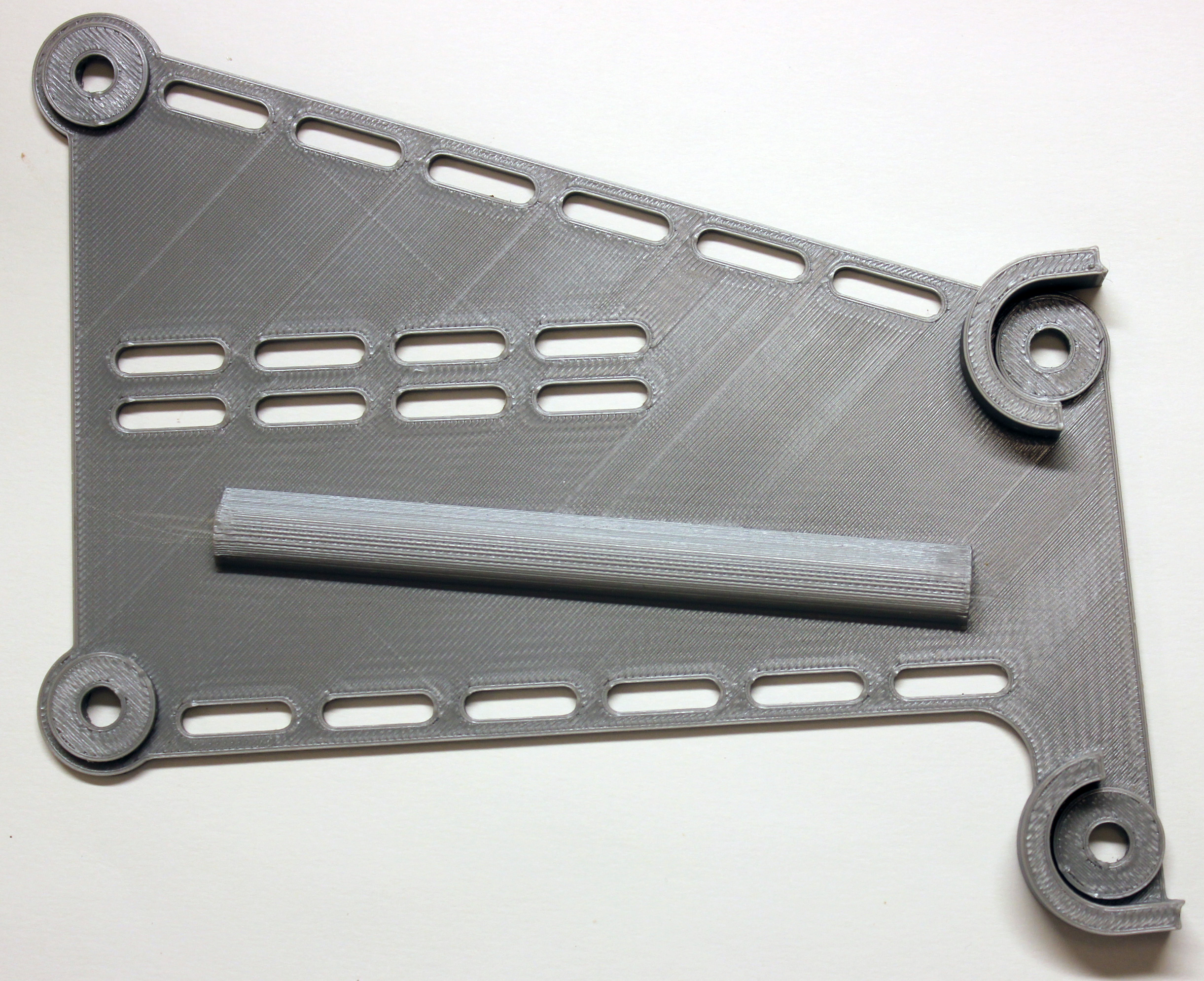
Forearm - top side. A coat hanger wire
was pushed through the string channel to clear sagging filaments from the ceiling of channel.

Forearm - bottom side

Forearm - side view

Palm - back view. Some manually-placed support was included
in this print to help with the significant bridging required in this part (PETG does not bridge well). The inner-top surface (not seen in photo)
was rough with some dangling filaments of first layer. This was smoothed with half-round file to good effect.

Palm - bottom side

Palm - front view

Palm - side view

Pins

Proximal Phalanges

Cuff - thermoformed. Cuff was immersed in boiling water
for about 30 seconds and then formed over the jig.

Forearm - thermoformed. Boiling water was poured into
an oven-proof rectangular dish, part immersed for about 2 minutes, then thermoformed over a 1.5 inch PVC pipe. Then ends of forearm
were immersed in boiling water about 30 seconds and formed to fit palm and cuff.

Assembled Arm. After assembly, the middle portion of the forearm
was heated carefully with a heat gun and formed so that palm is oriented approximately at 90 degree angle to cuff (red and black object in photo
is needle nose pliers used to prop up arm).

Arm with foam applied.

Arm with velcro applied.

Arm actuated, view at elbow joint. The retainer ring for the pin
has been removed. As the arm is actuated, tension of the strings causes the cuff portion of the joint to flex. This in turn applies a force
on the retainer ring in a direction away from the pin, causing the retainer ring to be pulled off the pin. Substituting a custom pin at this joint solved the problem.

Custom pin for elbow joint, tension box side.
Pins were printed on a raft due to small contact surface on bottom side. The Simplify3D software was set to automatically generate
support because the bottom of middle portion of the pin shaft is higher above print bed than the ends. For some reason, adequate support was only added under two pins, as seen in photo. The other three pins have partial support
under them which can't be seen in the photo, and do have defects in bottom surface. I only needed one pin, so used one of the pins with adequate support. I should also note that printing just one pin at a time does not result in a good pin because the layers are laid down too quickly. By printing five pins, this provides enough time for each layer to cool adequately before next layer is added, resulting in much better surface finish. Mechanical drawing of custom pin available HERE Mechanical drawing of original pin available HERE

Custom pin on left, standard pin on right for each of three views. The standard pin pops out during operation. The custom pin with re-designed end
stays in place during operation. The shaft of the custom pin is not flattened on top and bottom (as printed), but fully circular in cross section. The forearm hole for the pin (photo here)  is shaped in such a way that it can accept a pin that is fully circular. The circular end of pin on custom pin is thicker, resulting in a more squared-off inboard edge, which prevents the pin from being
ejected during operation of the arm. The slot of the pin on custom pin is rotated 90 degrees with respect to standard pin. My original thought was that this might prevent a compression of the pin. After more investigation I realized it was the lateral force applied by the strings during operation that was causing the pin retention ring to be forced off the pin. Therefore, a change of orientation of the pin slot may not be necessary.
is shaped in such a way that it can accept a pin that is fully circular. The circular end of pin on custom pin is thicker, resulting in a more squared-off inboard edge, which prevents the pin from being
ejected during operation of the arm. The slot of the pin on custom pin is rotated 90 degrees with respect to standard pin. My original thought was that this might prevent a compression of the pin. After more investigation I realized it was the lateral force applied by the strings during operation that was causing the pin retention ring to be forced off the pin. Therefore, a change of orientation of the pin slot may not be necessary.

View of pins with retaining rings. Here it is evident that
custom pin, on right, has better contact with retaining ring.

.stl files of standard pin and custom pin imported into Blender provides views of each model. This is an advantage when you don't have the CAD
file of the original parts. It is also possible to determine the dimensions of the parts in Blender. Blender is available for free HERE

Hand can grip and lift a half-liter bottle of water.

Finished hand.

Hand with fingers closed part way.

Hand fully closed.
![]()
![]()
Last update December 24, 2018